1. To understand what is meant by Fraunhoffer diffraction.
2. To observe single slit diffraction patterns and plot the intensity profile of the pattern.
3. Determine slit width from the diffraction formula.
Diffraction is the wave phenomenon which describes the deviation from straight line propagation of a wave when it encounters an obstruction. In the case of light waves both opaque and transparent obstacles cause this effect which results in shadow patterns on a screen which are quite different from those expected if light travelled only in straight lines.
There are basically two categories of diffraction effects. The first is Fraunhoffer diffraction, which occurs when the waves incident on the slit and the screen (detector) are plane waves. This diffraction is produced when both the light source and screen are effectively at an infinite distance from the given obstacle. Fresnel diffraction is the second type and refers to diffraction produced when either the source or screen or both are at finite distances from the obstacle.
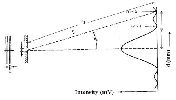
We can observe Fraunhoffer diffraction experimentally by using a collimated light source and (i) placing the viewing screen at the focal plane of a convex lens located behind the obstacle or (ii) by placing the screen at a large distance from the obstacle. The schematic of a single slit diffraction apparatus is shown in Fig. 10.1.
In this experiment we concentrate on Fraunhoffer diffraction patterns although you can observe the different patterns produced by Fresnel diffraction by placing the viewing screen close to the diffraction slit used.
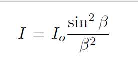
Fig. 10.1 shows a plane wave of wavelength λ incident on a slit width a. The diffraction pattern, intensity versus y is plotted in the figure. Wave theory predicts that the Fraunhoffer diffraction pattern intensity due to a rectangular slit will be of the form
(10.1)
where β = (ka sin θ)/2, k = 2π/λ, a = slit width and θ = angle formed by the light ray with respect to the system central axis. The minima in the diffraction pattern occurs when I(θ) = 0. This condition requires that
(10.2)
where, m is the order number in diffraction pattern and θm is angle measured with respect to system central axis to the mth order minima. The shape of this pattern is shown in

Figure 10.1: The Fraunhoffer diffraction pattern of a single slit.
Fig. 10.1. If θm is small, then
(10.3)
Further from geometry we have
(10.4)
where y = the distance between central maxima to the mth order minima point and D = distance between slit and photo diode (observed form instrument). Combining Eqs. 10.3 and 10.4, the slit width can be calculated as
(10.5)