1. To study the flux and emf in the coil as a function of time
2. To study the maximum emf and total flux as a function of the velocity of the magnet.
3. To demonstrate damping due to induced current
Faraday’s law of electromagnetic induction tells us that a change in magnetic flux gives rise to an induced emf " given by
(8.1)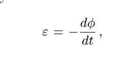
where φ is the magnetic flux. A simple apparatus has been designed, whose schematic
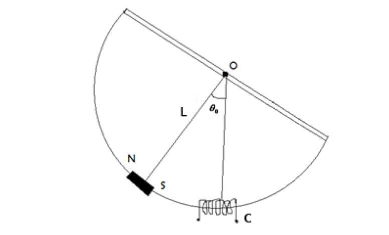
Figure 8.1: Schematic of the coil moving in and out of the magnetic field.
diagram is shown in Fig. (8.1), enables us to change θ at different rates through a coil of suitable area of cross-section. A rigid semicircular frame of aluminium is pivoted at the centre of the semicircle. The whole frame can oscillate freely in its own plane, about a horizontal axis passing through its centre. A bar magnet can be mounted at the centre of the arc and the arc passes through a coil C.
It is very instructive to study the emf, induced in the coil as the magnet passes through the coil while oscillating. In this experiment we will use a computer to monitor emf induced as a function of time.
The rate of change of flux through the coil is essentially proportional to the velocity of the magnet, as it passes through the coil. Choosing different amplitudes of oscillations can vary the velocity.
If I is the moment of inertia of the oscillatory system and ω is the angular velocity of the magnet, then the kinetic energy of the system is Iω^2/2 and potential energy can be represented by MgL(1 − cosθ) at any instant of time, where L is the effective length of the corresponding simple pendulum. If θo is the maximum angular amplitude and ωmax is the maximum value of angular velocity, then
(8.2)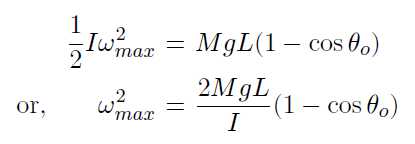
The motion can be regarded approximately as simple harmonic and its time period is given by
(8.3)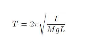
From Eq. (8.2) and (8.3), we get.
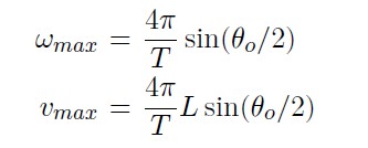
where vmax is the maximum linear velocity associated with ωmax. Angular amplitude θo is directly measured from the instrument. Velocity is computed by measuring T and θo.